


 Home /
Plannen van een installatie van een afschuiningsreducer: Maak van asvereisten een praktische aandrijfindeling
Rechthoek tandwielmotor: Bijpassende elektrische voeding, Variabele snelheid en remmen
26 okt, 2026
Plannen van een installatie van een afschuiningsreducer: Maak van asvereisten een praktische aandrijfindeling
26 okt, 2026
Het kiezen van een bovenliggende kraanversnellingsbak op basis van de hijs- of reisfunctie
26 okt, 2026
Vervanging van een industriële wormversnellingsbak: Wat te behouden en wat te heroverwegen
25 okt, 2026
Een afschuwingsreducer wordt vaak onderdeel van machineontwerpen waarbij de motor niet direct achter de aangedreven as kan blijven zitten. Het draaien van het stroompad kan een toegangsgang creëren, decrease the length of an assembly or create a mechanism that goes around a corner. Maar, selecting a housing that fits is just the start.
What is key for the mechanical designer/ for OEM engineer is the specification of the relationship between in, Uit, Snelheid en belasting. This guide will give an explanation on how to settle those relationships with Mingye T, K and B product families as references before the surrounding machine layout costs to change.
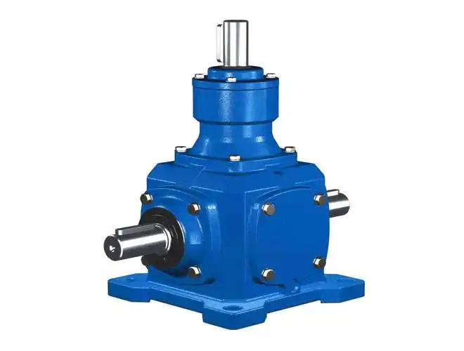
Determine if the machine needs a reduction or change of direction.
A pair of bevel gears is used to transmit motion between two shafts, whose axes intersect each other and are generally at right-angles. The ratio will decide whether the driven shaft will have the same speed or not. Just having a right-angle configuration does not define how much it will be reduced.
Mingye's T-serie spiraalafschuivende tandwielreminator lists ratios including 1:1, 1.5:1, 2:1, 2.5:1, 3:1, 4:1, en 5:1. A 1:1 configuration maintains the same speed as a standard configuration, but changes direction. It may be of relevance if the machine already is driven with the desired speed from a upstream drive.
Make sure that the design does not require that all requirements go through one direction changing unit when for a much lower final output speed, additional reduction stages would suffice. Determine the speed needed at each connection prior to selecting the family or ordering code.
Be sure to name all of the shafts before discussing rotation.
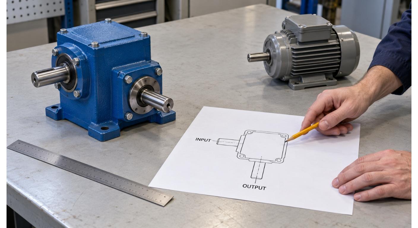
Identify input and output shafts on a layout drawing and which way each shaft is viewed. When people are talking about clockwise and counterclockwise directions, it may become unclear because they observe opposite ends of the shaft or reference to different sides of the machine.
Indicate physical motor location, shaft projections and unused connections. Do not assume that if a configuration has several accessible shaft ends, that these are independent outputs and have identical ratings. Discuss with the supplier the following: Permitted driving shaft, supported arrangement, and relationship with respect to rotation.
The speed relationship and operating conditions may be different when switching between power shafts. Before applying a nominal reducer in reverse power path or as a speed increase arrangement, get confirmation. A grouping of pictures of ends of shafts does not constitute a configuration drawing or approved operating description.
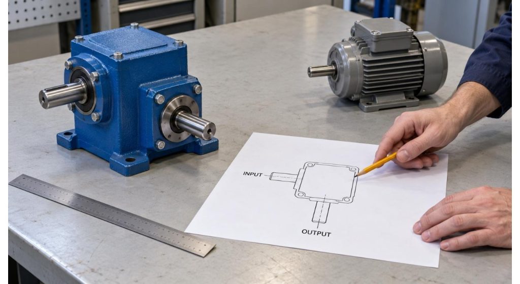
Select Separate Unit or Integrated Gear Motor.
The T-series is displayed ready to hook up to motors or other power sources. The quantity of an upstream motor can be arranged for separately but it would require additional space and support.
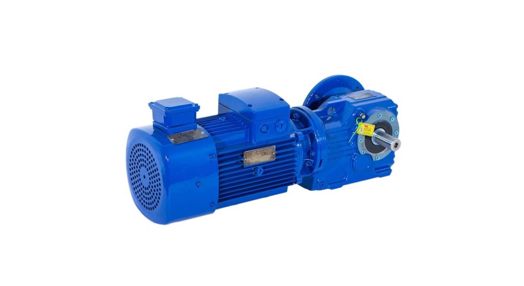
Mingye's K series Helical Bevel Gear Motor is an integrated drive, which integrates the functions of helical gear and bevel gear. Provides an alternate method of reduction and a perpendicular power path when a full gear-motor system is required for the machine.
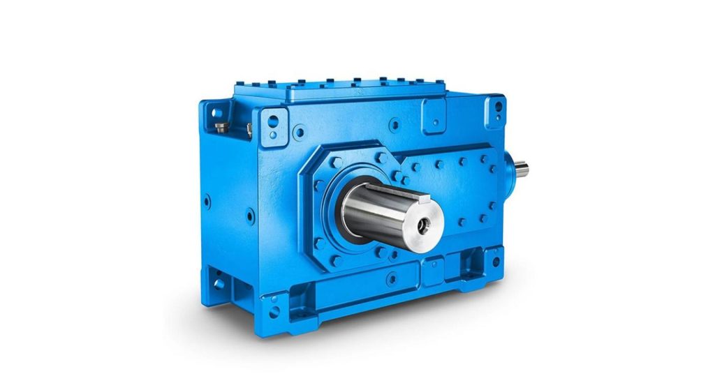
In the case of larger modular industrial configurations, Mingye's B Series gearbox offers cylindrical and spiral bevel gearing, featuring a number of input and output connections. Examine its true architecture rather than “growing” a small, T-series design by the way that it looks. The motor adapters, asverbinding, mounting references and the reduction arrangement should comply with the project.
If the proposed design has more than one mechanism, describe the speed, working torque and sequence of the operation of each mechanism. Make sure that the selected gearbox is suitable for that; several visible shafts do not make a free power-distribution function.
Input power should be able to meet the simultaneous requirements and transmission losses. There are several branches downstream served by one upstream shaft section and one shaft section serving only one branch downstream. Don't apply the same torque to all connections, review the load path.
Furthermore, mechanical linking is not a guarantee for correct synchronization in the working points. Relative movement can result from the clearance between the coupling, twist in the shaft, backlash in the gears, and other differences in the driven mechanisms. If time is critical, specify an allowable phase error, and check whole assembly, including shaft lengths and structural support
To determine the Overall Ratio Through the Complete Drive use the gear ratios of all the components.
If reduction stages are cascaded then their ratios cascade. Bijvoorbeeld, an upstream 10:1 reducer and a downstream 2:1 bevel stage result in an overall reduction of 20:1. The nominal final speed is 72 rpm with an input of 1,440 tpm.
This speed is not a measure of the torque capacity of either stage. The torque which the downstream unit is to handle must be that which the upstream is able to deliver after reduction and each coupling or shaft must be tested at the speed at which it will be running. Consider losses in torque and power transmitted.
The speed reducer ratio guide offered by Mingye is helpful in discussing about the required speed and load. Check that the ratios available are compatible with the machine target ratio, and then check allowable input speed, Opstartbelasting, reversals and duty for each ratio chosen.
The connection should be provided without over-loading the gearbox.
While it is true that a compact bevel reducer should not be the final destination for a long transmission shaft, is it not a good idea to have the gearbox hanging in the nose or engine room? Determine the bearings, couplings and mounting structure subjected to shaft weight and external radial and/or axial loading. Provide load positions as well as force values.
The gearbox foundation needs to maintain the necessary alignment. Confirm location of features and mounting rather than relying on bolts to pull a frame into position, if it is wrong. Appropriate allowance for thermal movement and tolerances required during installation must also be provided for in the connection design.
Check lubrication and mounting instructions for specific orientation and model being provided. Removal of guards for inspection, oil service (indien van toepassing), and coupling removal should be included in the layout. The smallest installation envelope doesn't always make for the most practical service arrangement.
Before releasing machine frame, approve the arrangement.
Include a drawing for Mingye that contains all the necessary information: the desired power flow, Schachten, Verhoudingen, rotation points, branch loads and mounting situations. Differentiate between the information given in the question and what you have assumed. Ask a proposed setting and any differences prior to concluding a machine structure.
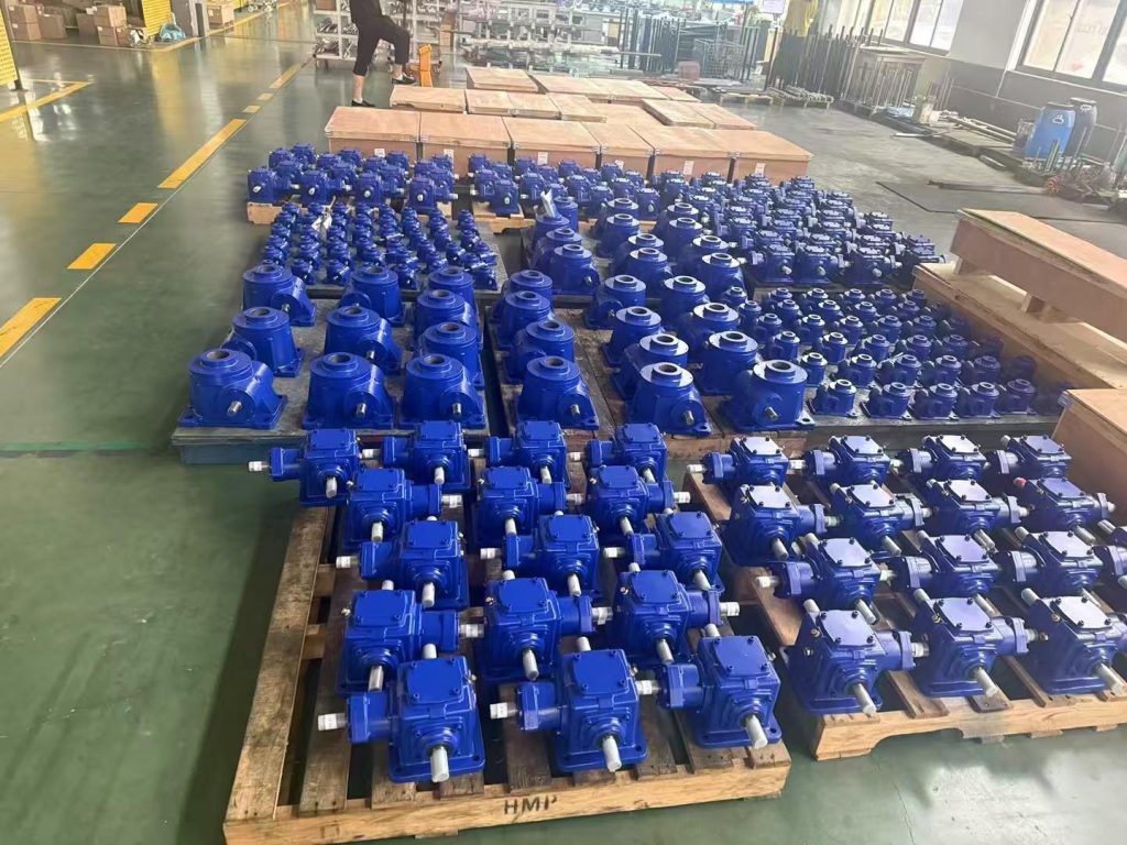
The site outlines manufacturing and dimensional inspection capabilities and the applicable checks are dependent on the product. Establish interface verification and running test (indien nodig) for the assembly chosen. The dimensional conformity does not determine the time of the branch or the behavior when it is loaded or the stopping function of the machine.
| Approved Item | Record to Retain |
| Shaft identification | Drawing with named connections |
| Rotation convention | Viewing direction and rotation notes |
| Connected mechanisms | Branch references and operating sequence |
| Mechanical interfaces | Supplier drawing revision |
| Final arrangement | Approval date and configuration code |
When connections and operation conditions are specified at the same time, a layout problem will be solved with bevel reducer. The clear arrangement drawing is a clear document that turns the general request for ninety degree transmission into a drive that all engineering, purchasing and assembly teams can continually reference.
Veelgestelde vragen
Q1. Is it always slower at the output with a bevel reducer?
Nee. Unit changes direction but does not lose speed 1:1. Check the input shaft and actual ratio for proposed connection.
Q2. Is there an input accessible shaft that can be used?
Do not assume this. Request that supplier provide confirmation of the allowable driving shaft, Snelheidsverhouding, lubrication requirements and ratings of the arrangement.
V3. Is multiple output shaft end equal to multiple output torque?
Nee. Internal load paths and shaft connections need to be reviewed. Check the loading limits of individual mechanisms and of the combined mechanisms before distributing the power to them.
Q4. Will the mechanically driven outputs stay in sync 100%?
Niet automatisch. Relative position may vary due to shaft twist, Tegenreactie, coupling clearance, enzovoort. Indicate the time requirement for the entire assembly.
V5. Are bevel reducer holding devices?
Don't assume that it retains a load when it loses power. If restraint is necessary, state and check the proper brake or other means of holding.
Deel op Social:


Neem contact met ons op
In dit artikel
Rechthoek tandwielmotor: Bijpassende elektrische voeding, Variabele snelheid en remmen
26 okt, 2026
Plannen van een installatie van een afschuiningsreducer: Maak van asvereisten een praktische aandrijfindeling
26 okt, 2026
Het kiezen van een bovenliggende kraanversnellingsbak op basis van de hijs- of reisfunctie
26 okt, 2026
Vervanging van een industriële wormversnellingsbak: Wat te behouden en wat te heroverwegen
25 okt, 2026